0032Automated pallet planter watering
2025-12-31
I built an automated watering system for my pallet planter: It consists of a pump, a soil moisture sensor, and is integrated into my Home Assistant setup so that the pump can automatically turn on and off as needed.
When I first tried this project a few years ago, I bought a pump, some hoses, and designed and 3d printed connectors and drippers for the hoses. None of this worked well: The pump was rather loud, it needed 12V (5V would be better, I need 5V power anyway for the microcontroller and sensor), one had to be careful to not run the pump dry (at least not for a longer amount of time), and the 3d printed parts didn’t fit very well and were a hassle to print.
This time I decided to do it differently: I bought an inexpensive pot watering kit that included pump, hoses, and all the necessary connectors and drippers. It also contained a control unit with a (mechanical) programmable timer. That part I discarded, but everything else I repurposed for my project.
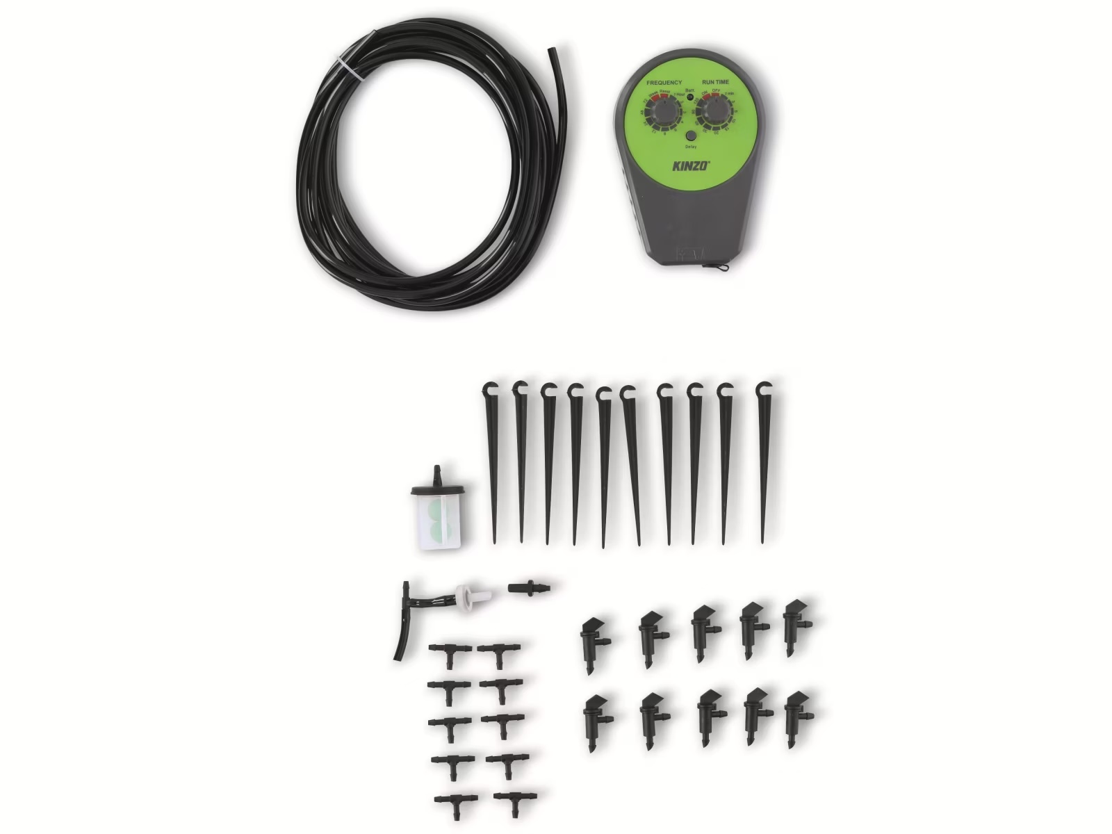
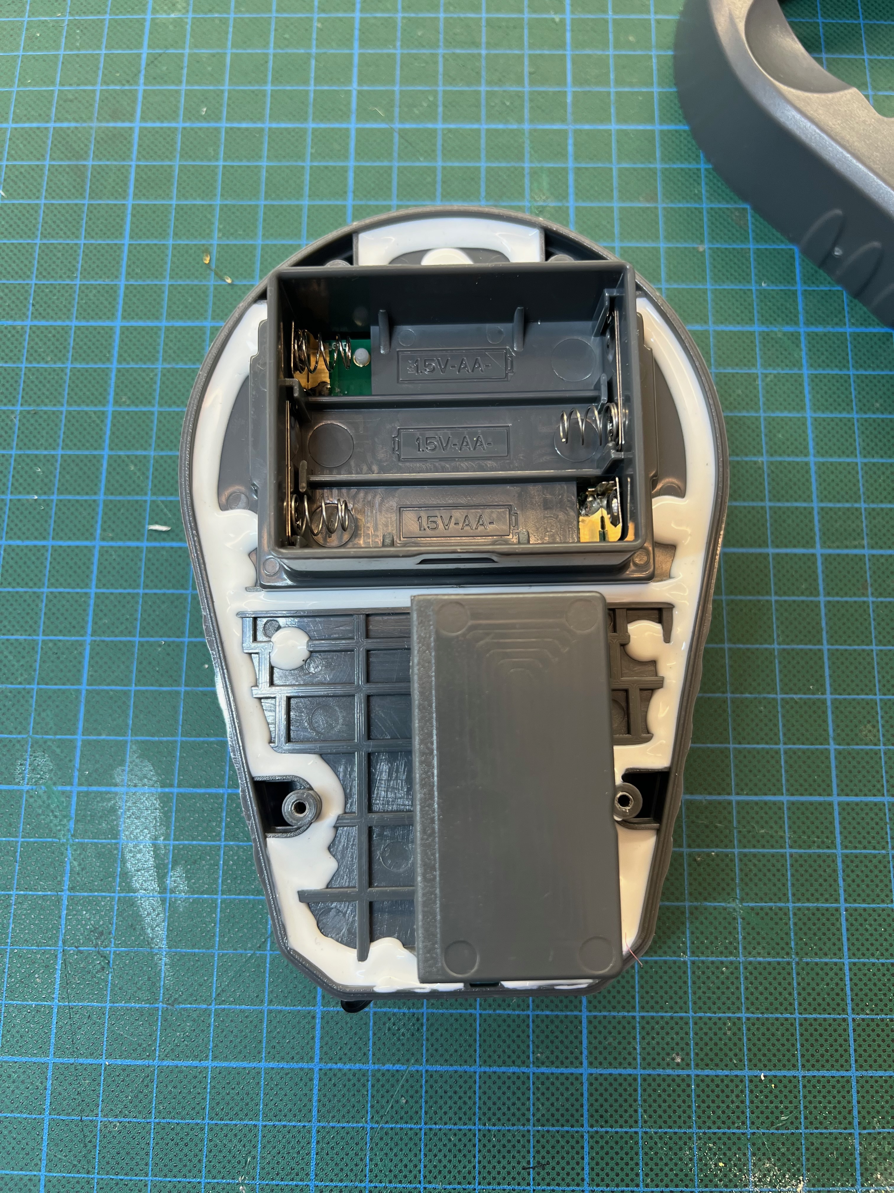
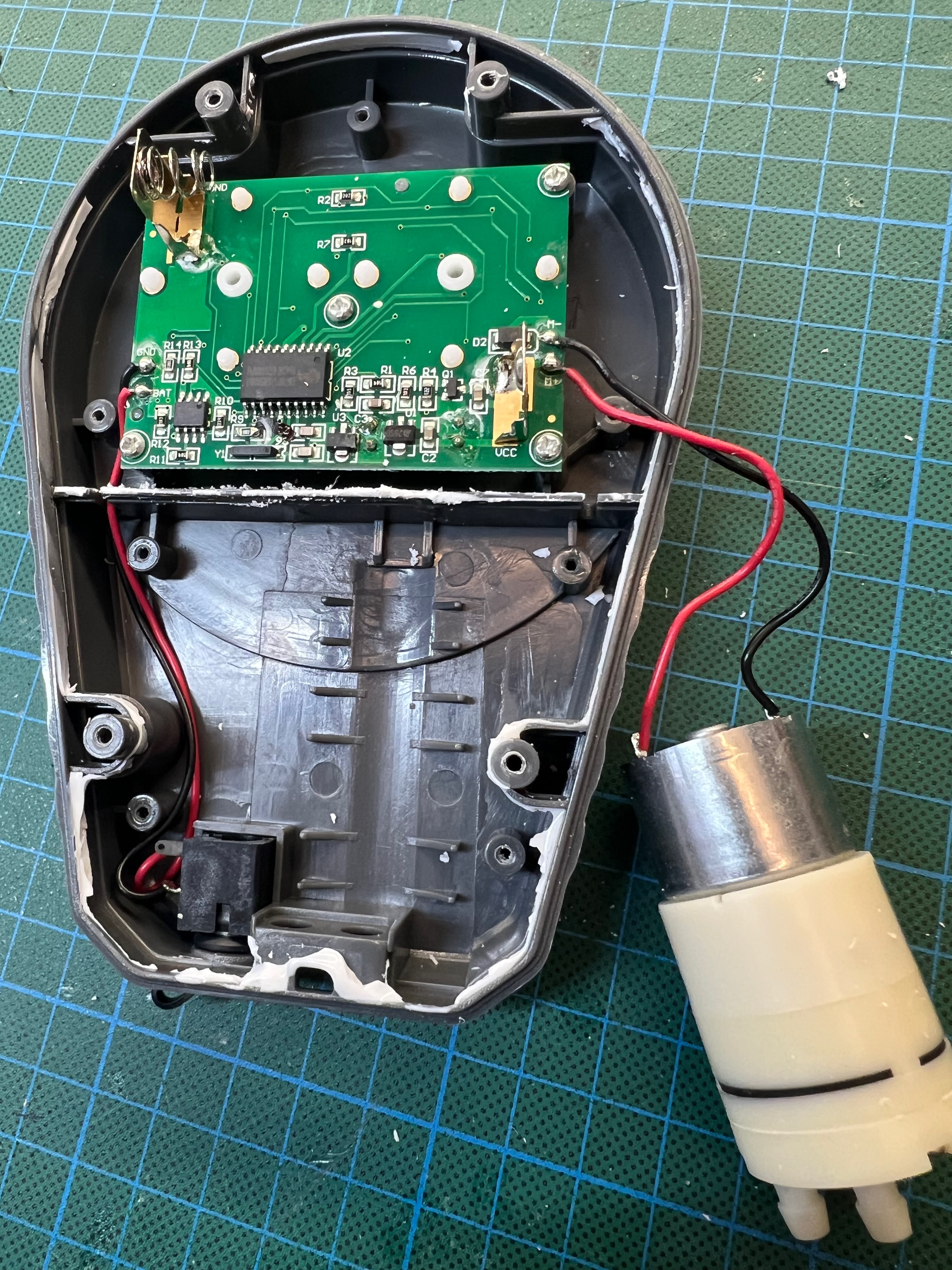
The pump is a decent diaphragm pump. Like all diaphragm pumps, it’s not an issue if it runs dry, making it an excellent choice for automated watering from a small reservoir. And it runs pleasantly quiet.
In total, even including the control unit I didn’t need, I paid considerably less for this kit compared to buying all components individually.
Interfacing with Home Assistant
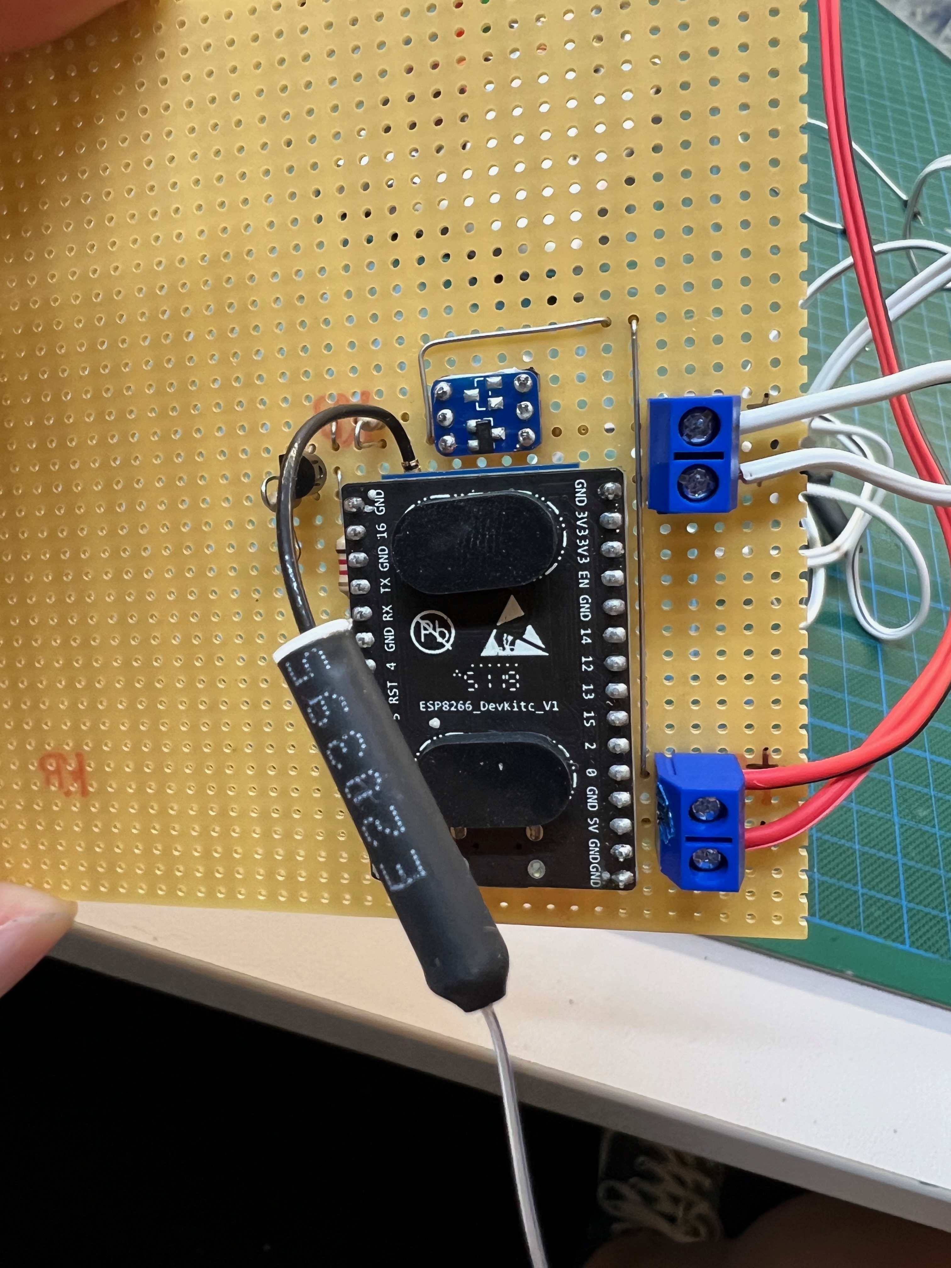
To control the pump from Home Assistant, a microcontroller was needed. I chose an ESP8266 development board that can be powered with 5V. As the pump also runs fine on 5V1 I can use a standard 5V wall wart as power supply.
For turning the pump on and off I used a very simple highside switch circuit2 controlled by one of the ESP8266 GPIO pins. Add two terminal blocks to connect the pump and power supply, and the first prototype was ready:
Creating the firmware with ESPHome
Using the ESPHome builder one can easy (and very quick) create custom firmware builds for microcontrollers, that then expose specific resources to Home Assistant. In my case I simply declared that GPIO4 should be exposed as a “switch”.
esphome:
  name: palettenbeetpumpe

esp8266:
  board: esp_wroom_02

# Enable Home Assistant API
api:
  encryption:
    key: Nothing to see here ...

ota:
  - platform: esphome
    password: ""

wifi:
  networks:
  - ssid: My WiFi
    password: My WiFi Password

switch:
  - platform: gpio
    name: "Pumpe"
    pin: GPIO4
Measuring humidity
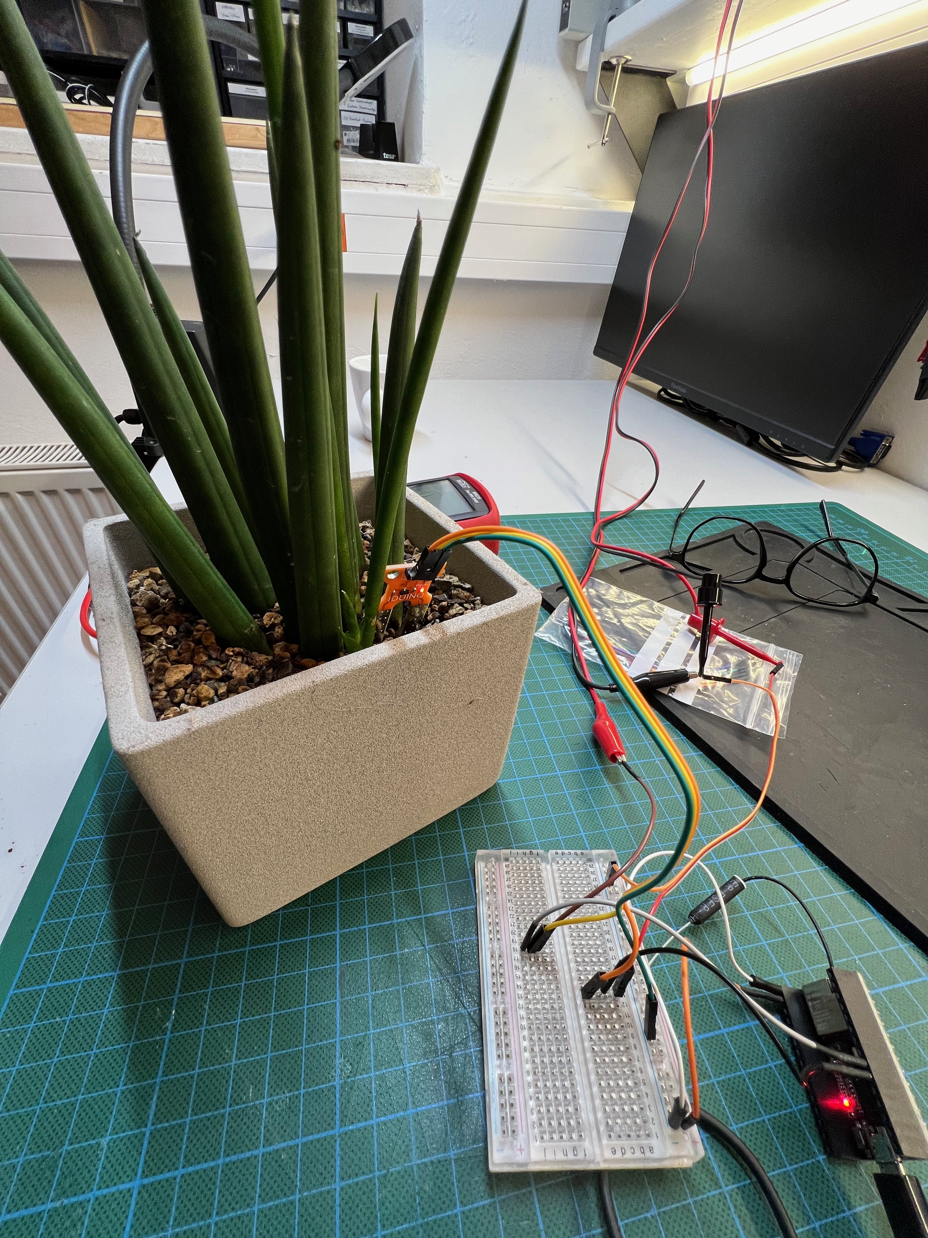
I also wanted to measure humidity inside the planter, for automated watering.
Leave a comment