0015Cookie Cutters from the 3D Printer
2018-01-25
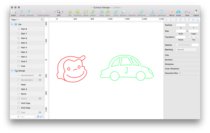
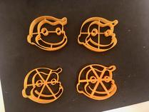
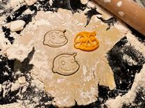
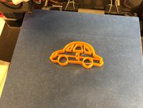
For holiday season I made personal cookie cutters for my niece and nephew: A monkey head modelled after Curious George, and a car with an initial on it.
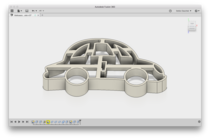
I started in Sketch where I created simple vector drawings of the two motifs. After exporting the drawings as SVG I then imported them into Fusion 360 to make real 3d objects by extruding the paths along the z axis. Finally I added some struts to hold the individual parts together.
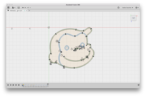
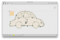
To prepare the drawings for extrusion I had to first thicken the curves: Fusion 360 doesn’t care about the stroke widths in your SVG, paths will be imported as zero-width curves. But you can recreate the original stroke width using Fusion’s “Offset” function as seen below:
The “Offset” function generates a new path at a fixed distance from a given path. So to recreate the original stroke width, simply add an offset path on each side, using half of the total stroke width as offset value. You then need to close all “loose ends” by connecting the offset paths at their ends. Using straight lines would be the easy solution, but semi-circles look more fancy (see the “J” on the car for an example).
Recreating the stroke widths in Fusion 360 is a bit tedious, but it has one big advantage: If you later want to change the widths, you can do so by simply adjusting the offset value (which requires only a single change if you used a parameter for the offset)1.
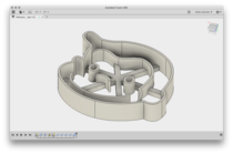
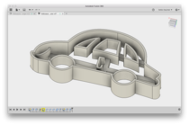
With the drawings all prepared, I extruded them along the z axis. Extrusion is straightforward except for one detail: If you look at the models upside-down you’ll notice that some parts differ in height: This is because the inner parts should only “engrave” the dough, not cut it. The simplest way to achieve this is by doing two separate extrusion steps with different settings2.
Now what are suitable dimensions for stroke width, extrusion height, and offset?
After creating several trial prints with different settings and trying them out on real dough I found that walls 1.25mm wide give a decent kind of stability, and an overall height of 12mm with the inner parts offset by 4mm work well for cutting and engraving the dough. These values (especially the offset) strongly depend on the thickness of your dough, though3.
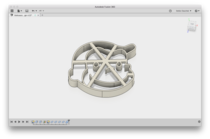
Because each motif consists of several disconnected pieces, struts need to be added to keep everything together in one part. The first picture shows several variants I experimented with, starting with thin cylindrical struts and eventually arriving at rather massive ones featuring a square 3⨉3mm cross section. I also varied the placement and number of struts until the models felt solid enough to withstand being handled by toddlers.
Early designs had the struts vertically centred (because of symmetry!), but I soon realised that having the struts flush with the top makes for easier printing: Just print the cutters upside down and you won’t need any support structures or bridging at all.
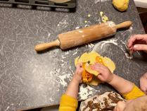
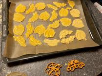
After the final prints were done it was time for some baking action!
Lessons Learned
- Avoid small or (partially) covered areas and tight angles – if you don’t stick to this rule, dough will stick to your cookie cutter4, making it hard to clean after use. I learned this the hard way with the car’s headlight and some of its window corners. Toothpicks came in handy when it was time for cleaning.
- Also avoid thin features as they will break off when separating the dough from the cutter (see George’s quiff for an example).
- Don’t eat too many cookies at once.
-
On the other hand, now that I know which stroke width will work fine I might as well do this step directly in Sketch the next time: With “Convert to Outlines” it’s possible to create a new path along a stroke’s outline (so a thick straight line will be converted to a rectangle etc.). Paths created that way can be extruded without further post-processing in Fusion 360. ↩
-
The settings depend on the extrusion’s direction: If extruding downwards (negative height), you want to specify a lesser height for the inner parts. If extruding upwards (positive height), use the same height as for the outer parts but additionally specify an offset from the ground plane. ↩
-
D´oh. ↩
-
Sorry. ↩

Leave a comment