0029A Four-Joystick-Adapter for my C64
2023-01-15
The C64 has two joystick ports – but with a bit of custom hardware it’s possible to connect even more joysticks. Let’s get ready for four player games!
I recently acquired “Muddy Racers”, an adorable single-screen racing game for the C64 (see the trailer on YouTube).
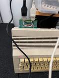
The game supports up to 4 players with joysticks, however: The C64 has only two joystick ports. The solution? A custom adapter for one of its extension ports, to which two additional joysticks can be connected.
Various such adapters exist, with the one from Protovision / Classical Games being most widely used and supported by many games. It’s also very simple, hardware wise. You can buy it from Protovision or build it yourself. Obviously, I chose the latter.
Quick and (a bit) dirty
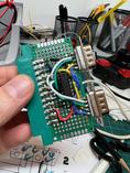
I had all the parts lying around, but the connectors for the user port and joysticks were the kind meant for soldering wires onto it. I wanted to solder them directly to a circuit board though (mainly to avoid having to build some kind of enclosure for holding everything in place).
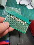
The soldering tabs of the user port connector are spaced 3.81mm apart, so that on a standard 2.54mm prototype board every second tab ends up exactly between two pads. Doesn’t look very pretty but it works; as long as you are a bit careful while soldering there won’t be any shorts.
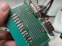
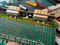
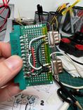
The tabs of the joystick connectors also don’t line up with the pads on the prototype board. Luckily, one of the pins on the connector is not used at all1, thus we can simply remove the corresponding tab. The remaining four tabs then just so fit to the tabs on the board if carefully aligned.
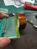
There’s a second problem though: The connector has two rows of tabs. The board fits exactly in-between (good!), but the tabs on the top and bottom would get shorted (bad!). Solution? Use a small strip of kapton tape2 to insulate the board from the tabs.
Apart from the connectors there is only one electrical component on the board: An IC acting as electric switch3. I soldered it to the centre of the board, and then completed all connections using silicon-insulated wire4.
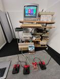
And that’s it: Now I can connect up to four joysticks simultaneously!
-
There are two more unused pins, but they belong to tabs in the bottom row of the connector. ↩
-
Also known as polyimide tape. It has successfully been used to fix leaks on the International Space Station (even twice!), so it will probably be good enough for a C64 board, too. ↩
-
Technically a quad 2-input multiplexer. It is used to alternately connect the signals of one of the joysticks to the user port, reducing the number of required pins. ↩
-
Compared to usual, PVC insulated wires these silicon wires have the advantage that the insulation doesn’t get damaged if you accidentally touch it with the soldering iron. Also they are more flexible. ↩
Leave a comment