0012Improving my sd2iec’s Power Connector
2017-03-08
When I originally built the sd2iec for my C128, I improvised a simple power connector for the cassette port. It worked, but felt kind of wonky. Time to improve!
The C64/C128 has a cassette port implemented as 6-pin edge connector1. Two of the pins are connected to 5V and GND, and these can be used to power the sd2iec.
I didn’t have a suitable edge connector when I built my sd2iec, so I created a simple power connector out of some spare parts. It did work quite well, but in the meantime I got hold of a 1530 datasette2 with an original cassette port edge connector: Time to make a real connector for the sd2iec!
However, I want to keep using the datasette in the future, too. So instead of simply cutting off its connector and soldering it onto the sd2iec power cable, I decided to go with a more modular approach: Build some kind of adaptor with the cassette port edge connector on one end and some kind of standard female plug on the other end. If I then soldered matching male plugs to both the datasette and the sd2iec, I could use the adaptor with either of them.
Side note: Some time ago I also acquired a 1531 datasette3. It’s almost identical to the datasette for the C64/C128, but instead of the edge connector it features a Mini-DIN-7 connector. With a suitable adaptor it can be used with the C64/128, too.
This means if I’d build a Mini-DIN-7 to edge connector adaptor, I could use it for all three devices: the 1530, the 1531, and the sd2iec!
And that’s what I did: I cut the 1530’s cable in half, soldered a Mini-DIN-7 male plug to the part connected to the device and a female plug to the other part connected to the edge connector. Then I removed my original handmade connector from the sd2iec’s power cable and replaced it too with a Mini-DIN-7 male plug. (For the 1531 there wasn’t anything to do at all, as it already came with a Mini-DIN-7 plug.)
Here are some photos and the wiring diagram for the adaptor:
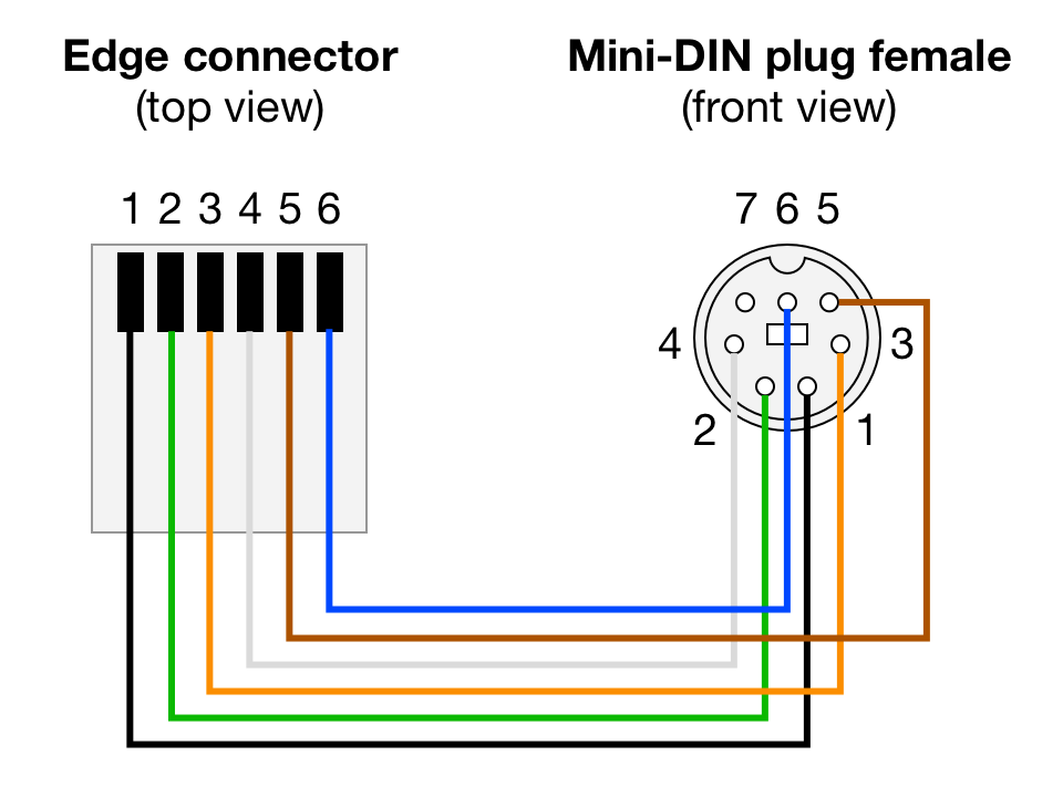
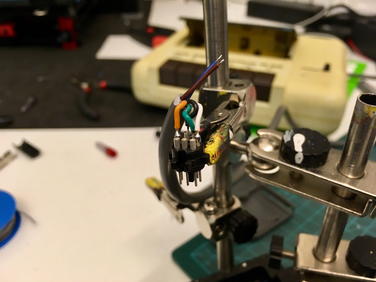

-
Technically there are 12 pins: 6 at the the top, and 6 and the bottom. But each top pin is connected with its respective bottom pin, so there are only 6 distinct pins. ↩
-
To be exact: The datasette I got is not an original Commodore 1530 but a 3rd party clone called “noris 1535”. But this makes almost no difference. ↩
-
The 1531 was meant to be used with Commodore models from the 264 line like the C16 and Plus/4. ↩
Leave a comment