0019Building a Faux Neon Sign Using LED Strips (Part 1)
2019-08-31
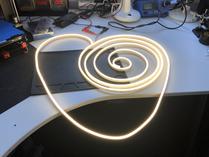
LED strips that look like neon tubes? Terrific! I’ve always wanted to build a neon sign!
The strips are about half a centimetre wide and available in various colours1 from suppliers like Adafruit. I bought mine – 5m of warm white – here in Vienna at semaf electronics.
Individual neon letters are nice, but they are even nicer when forming complete words. So what should the sign read?
I wanted to keep scope limited as all my projects tend to become way more intricate in the making anyway. A few letters had to be enough. So maybe a single word only? A short one?
“Was?” (german for “What?”)
Not only is “what?” a very good (even fundamental) question, but it also has the advantage of being rather short. And it’s one of the rare occasions where the german equivalent – “was?” – is even shorter. Three letters and a question mark: That looked reasonable.
Now I needed to find a suitable font. I browsed through a lot of lettering fonts on myfonts.com for inspiration, but found nothing really convincing. In the end I created the letters from hand, taking inspiration from some of the fonts I had seen:
The strokes look a bit thin, don’t they? Well the LED strip, too, is rather thin (5mm), and I tried to match the stroke width to the actual width the completed letters would have when mounted on the sign. And when being lit and glowing, the thin letters would look just perfect – or so I thought. But more on that later.
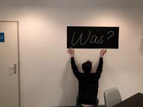
Speaking of dimensions: I had a vague idea of making the sign about 50cm high. Scaling the letters up to this size showed that the sign then needed to be about 120cm wide. Both dimensions looked reasonable. However, I’m notoriously bad at imagining how things of a specific size will look like in real life – so I decided to build a prototype first.
Foam Board Prototype
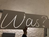
Foam board2 is a great prototyping material: It’s lightweight, sturdy, and easy to cut with a cutting knife … or with a CNC mill.
Okay, using a CNC mill to cut foam board may sound a bit overkill. But why not? We recently added a small CNC mill3 to our shop and I wanted to practise working with it anyway. So here it goes mills:
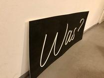
The mill has a working area of about 60x42cm4, meaning the cutting had to be done in two passes: First the “W”, then the “as?”. Being only 5mm wide the resulting letters were a bit fragile, but still sturdy enough to use in a prototype.
The base plate of the prototype was also made out of foam board. However, white lettering on a white plate doesn’t exactly win the “best contrast ratio of 2019” prize, so I did a quick paint job using black spray paint.
You did notice the missing dot below the question mark, didn’t you? Here’s its story: Cutting a closed loop (in this case: an oval) obviously results in its inner part becoming detached. In my case, as soon as cutting the dot’s outer diameter had been completed, the spinning motion of the milling cutter launched the now detached dot for an impressive sightseeing flight across our shop.
With the dot gone, cutting the inner diameter was obviously no longer necessary (or even possible).
Of course there are strategies to avoid this kind of problem:
- Using tabs (like in stencil fonts) to keep inner parts attached.
- Mounting the material to the sacrificial plate5 across its entire surface (e.g. using glue).
- Reversing the order of the cuts: Just make sure that cuts along the inner diameter are done first6.
You see, in theory I know about all this. In practice – well, at least it affected the prototype only. (However, there would still be other problems with the dot instead later on …)
The Sign’s Base Plate
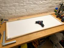
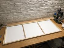
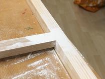
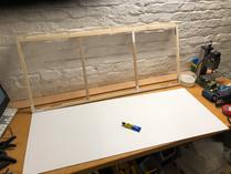
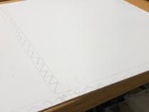
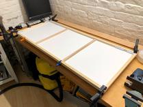
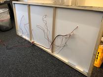
For the base plate I used a 3mm polystyrene plate (“Bastlerglas❖”), mounted on a frame of timber beams (22×22mm). The timber beams were connected using angle brackets. Plastic glue (“UHU Hart❖”) was then used to bond plate and beams.
Basically there are two possible ways how angle brackets can be used to create a frame like this: They can either be mounted on the back side (facing the wall), or they can be mounted inside the frame (facing each other). The first method is easier to build, but the second makes the frame look better. So I decided to use … both, at least temporarily: I started with angle brackets on the back of the frame (see first picture). This made the frame sturdy enough so that I could safely tilt it, making it easy to access the inside of the corners and to mount the inner brackets. The brackets on the back side had then done their duty and were removed again.
Making the LED Strip Segments for the Letters
To create the faux neon letters the LED strip had to be cut7 into shorter segments, each segment matching one of the letters’ strokes. Then power wires had to be attached to each individual segment – but how?
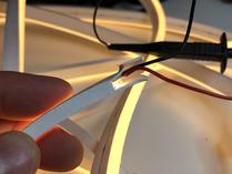
The usual way is to scrape off a few millimetres of silicone coating at the end of the strip to expose the solder pads below, then attach the wires there. Pro: Easy to do. Con: When looking at the strip from the front, both the solder pads and the wires are visible. That’s … ugly!
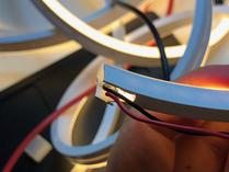
To hide the wires I decided to hollow out the end of the strip instead, by removing about 3cm of the inner silicone8. Inside the hollowed part I then removed some LEDs so that I could access solder pads which were still concealed by the outer silicone. Attaching wires to these pads and making them leave the strip vertically so that they can pass through a hole in the base plate directly below makes the wires completely invisible from the front.
Later on I would discover that this solution has two drawbacks: First, removing LEDs from the end of strip means that the strip’s last few centimetres are no longer lit. And second, the hollowed part becomes quite wobbly and thus difficult to attach to the base plate.
However, for now I thought I had successfully solved the wire attachment problem, so I went on creating the individual LED strip segments. Here the remains of the prototype came in handy: I could simply insert the strip into the cutouts to determine the correct length for each segment.
Attaching the Strips to the Base Plate
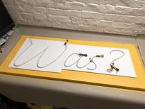
Now I had to attach the strips to the base plate. Here the remains of the prototype came in handy a second time: With the LED segments still inserted I shifted the cutouts around on the base plate to find a position where alignment and padding looked just right. I then marked the positions of the letters, as well as the places where holes for the power wires needed to be drilled.
Drilling the holes was straightforward (polystyrene is very easy to handle) – ready for attaching the strips! Until now I hadn’t thought much about how to fasten the strips, though. Maybe using plastic glue? This seemed to be the simplest solution, so I decided to attempt this first. If it wouldn’t work I could still try to find something else.
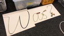
However, it actually did work. I kept the strips inserted into the cutouts while applying the glue – this helped tremendously, keeping the strips in place until the glue had set.
The bond even turned out to be quite firm – but once again the question-mark-dot proved itself as the project’s problem child: The tight bend caused by its small radius generated forces too strong for the bonding provided by the glue. In other words: The strip segment for the dot kept coming off the base plate, even after multiple attempts of gluing it down.
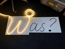
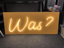
But never mind – I couldn’t wait any longer to see the sign9 being lit!
Looked great … at first. However, the longer I looked at it the more things started bugging me:
- Light was leaking from the ends of the LED strips, creating ugly bright spots on the base plate (look at the centre of the “W” for example). For a short moment I thought about stating “it’s not a bug, it’s a feature!” – but truth is that it simply was looking un-neony.
- The hollow ends of the strips (where I had attached the power wires) were noticeably darker10 than the rest of the strips. It’s not really visible in the photo, but in real life the effect was pronounced enough to annoy me.
- And the most important shortcoming: The letters were looking way too thin and fragile. In retrospect that’s something I might had already suspected after finishing the prototype – but I also might had decided to ignore this suspicion, hoping that the problem would magically disappear when the sign was finished.
And of course my personal nemesis, the question-mark-dot, was still haunting me: Still no idea how to permanently attach it to the base plate …
To be continued …
In part 2 of this post I’ll describe how I tried to fix these issues and eventually ended up with a beautiful sign that’s now adorning our office kitchen.
-
There’s also an RGB variant, but it is twice as wide and thus less flexible. And of course more expensive. ↩
-
Also known as „Kapa-Boards“, available for example at Modulor. ↩
-
A cute little Stepcraft D 600. ↩
-
These dimensions played a key role when I decided to make the sign 50cm high: Any larger and the “W” letter would no longer have fitted in the mill. ↩
-
“Sacrificial plate” is indeed the official term for the plate below the material being cut. Cuts through the real material extend a millimetre or so into this plate to make sure that the real material has been cut through completely. ↩
-
Of course this method is applicable only if the piece you’re after is the donut-shaped part between the two diameters (like in my case of cutting out letters). If you want to make a stencil, you need to use tabs instead. ↩
-
Like a regular LED strip the neon strip can not be cut at arbitrary positions but only at regular intervals (between groups of 3 LEDs, that is about every 5cm). ↩
-
To remove the silicone I made two deep cuts from the bottom parallel to the long side of the strip and then used pliers to carefully rip out the inner silicone. ↩
-
Except for the question mark’s dot, obviously. ↩
-
Remember that I had to remove some LEDs to get access to the solder pad inside the strip. ↩

Hello,
Great explanation!
I have used to do it with acrylic using cnc machine and i am facing difficulty choosing the size of the font.
The width of the LED is 6mm.. whence I choose the font and start to type any word. The size of the width weather 1.20 cm ( large) or 4mm too small.
Do you recommend that I use certain font or I do it manually ? Tbh it tooks me many hours doing one sign .
Best regards
weather the w