0022Transforming a Vintage Rotary Phone Into a Jukebox
2020-01-26
The toddlers’ love to “use” their vintage phone – and now it even plays audio clips when they dial a number!
.")
Let’s face it: Rotary phones were cool to interact with. The physical act of slowly rotating the big spring loaded dial, the satisfying click-click-click when the dial rotated back into its initial position … no wonder the toddlers, too, are fascinated by this device – even though they’ve never seen anyone actually making a phone call with one of these (and probably never will).
So I started thinking: How about making this phone play audio clips when you dial a number – transforming it into kind of a phone-jukebox?
Of course the experience should be as authentic as possible, so there also had to be a dial tone after picking up the handset, and a busy tone when the audio clip ended.
In other words: I decided to build the world’s first ever recorded information service (“Tonbanddienst”1) with an effective audience of only two people.
Planning
To realise this idea I needed a device that could store and play audio clips, would fit into the phone2, and could efficiently be powered from a rechargeable battery. What were the options?
- Using a Raspberry Pi: The Pi comes with an onboard audio jack, and being a full-fledged computer it easily handles all imaginable sound formats. Also, the SD card that is needed for its operating system has more than enough space left to store plenty of audio clips. Downsides: Consumes a lot of power, takes a rather long time to boot.
- Using an Arduino: Low power consumption, almost instant boot-up. However, using an Arduino for playing audio isn’t as simple as it might seem: There are several experimental audio libraries, but they only support some of the newer Arduinos like the Due or Zero3, and still require additional external amplifier circuitry. Finally, because of the Arduino’s limited internal memory an additional SD card reader would be necessary for storing the audio files.
- Using the Adafruit Audio FX Mini Sound Board: This is a standalone device with 16 MB built-in storage for audio files. Playback can be controlled from a microcontroller over a serial connection4. It boots up in about half a second, uses little power, and has an onboard amplifier with enough power to easily drive the handset speaker.
It wasn’t hard to realise that using the Adafruit Sound Board would be the best choice. Additionally I’d need a microcontroller5 to decode the numbers dialled on the rotary dial and to control the sound board.

Interfacing With the Phone
How to interface with the original components in the phone? Time for a look inside!


Turns out the innards of these old phones aren’t that complicated at all: A compact mainboard, a handful of analog components, and a surprising amount of tab terminals. This makes hacking the phone easy, because handset, rotary dial, and external phone cable are all connected to tab terminals and thus can easily be unplugged. Additionally, there are quite a lot of unused tab terminals.
The large transparent part at the bottom right of the mainboard is the hook-switch: A spring-loaded mechanical switch that gets activated when the handset is taken off the cradle. It consists of 4 separate switches, each with 3 contacts for both ”normally open” and ”normally closed” usage – again, very convenient for hacking the phone!
My aim was to keep the phone and its original circuitry intact as much as possible. Thanks to its modular structure this turned out to be easy:
My circuit would need connections to the handset speaker and the rotary dial. Both have cables ending in crimp receptacles, so by including appropriate tab terminals on my perfboard I could simply unplug these components from the mainboard and connect them to my circuit instead. No need to change the original mainboard or any of the cables!
The other component my circuit somehow needed to interface with was the hook-switch. I wanted it to become the device’s main power control: Take the handset off the cradle – the circuit is powered on. Put the handset back – power is cut.6
I had already found out that the hook-switch consists of 4 separate switches. Quite likely that not all of them were actually in use – let’s check!
To make it easier to trance the connections on the mainboard, I took photos of both sides and created a composite picture:

Turns out there is indeed an unused switch, connected to the tab headers “Bl1” and “Bl2”. So if I connected my circuit to “Bl1” and the power supply to “Bl2”, I’d get exactly what I wanted: Power only when the handset was off the cradle.
Decoding the Dialled Number
Now it was clear how the circuit would be turned off and on – but how to decode the signals from the rotary dial? (Remember the sound board should play different audio clips according to the number you dialled.)
When you dial a digit on a rotary phone, you put your finger on that digit, turn the spring-loaded dial clockwise until you hit the end-stop, and then release the dial, which causes it to rotate back into its initial position. Electrically, two things happen during this sequence:
- A contact gets closed as soon as you start turning the dial, and stays closed until the dial is back in its initial position – generating kind of a “dialling in progress” signal.
- While the dial rotates back into its initial position it repeatedly triggers a second contact, producing a sequence of short pulses. The farther the dial was turned, the more pulses are generated.7 Because of the way the digits are arranged on the dial, the number of pulses actually corresponds to the dialled digit: Dialling
1results in a single pulse, dialling6produces six pulses and so on.8
Here’s what the dialling process looks like on an oscilloscope (look at the blue pulses and how their number corresponds to the dialled digit):
To decode the dialled digit with a microcontroller we simply connect both these signals to GPIO pins, and then do some pulse detection and counting:
// Return currently dialled digit (0-9), or -1 if the digit was not recognised
// correctly (0 or more than 10 pulses detected). Dialling must already have
// started (`diallingSignalPin` active).
//
// `diallingSignalPin` is assumed to be active-low; for `digitSignalPin` it
// doesn’t matter (edge detection works with both active-low and active-high).
int8_t RotaryPhoneDialDecoder::readDigit() {
  uint8_t digit = 0, last = LOW, current = LOW;
  while (digitalRead(diallingSignalPin) == LOW) {
    current = digitalRead(digitSignalPin);

    // Count how often digitSignalPin toggles its state (edge detection).
    if (last == LOW && current == HIGH) digit++;

    last = current;
    delay(10);
  }
  if (digit < 1 || digit > 10) return -1;
  return digit == 10 ? 0 : digit;
}
See GitHub for the complete source file.
Prototyping the Circuit
Knowing how to theoretically decode digits is nice, but actually doing it is even better. Time to prototype the circuit!
There wasn’t a lot to do anyway: I stuck both the sound board and the microcontroller into a breadboard and created various connections using jumper wires:
- The handset speaker was connected to the sound board’s line output.
- The rotary dial was connected to two of the microcontroller’s GPIO pins.
- A two-wire serial connection between the microcontroller and the sound board was put in place.
- The pins for programming the microcontroller were connected to a breakout board that allowed for easy connection of a standard 6 pin ISP cable9.


Surprisingly everything worked at the first try. After uploading the initial version of the software, dialled digits were already decoded correctly, and the matching audio file was played from the sound board through the handset speaker:
At this stage I was still using example audio files. Later they would get replaced by some of the toddlers’ favourite songs and short stories.
Playing around with the prototype also quickly revealed some shortcomings in the user experience:
- The dial tone needs to stop as soon as you start dialling (here the “dialling in progress” signal comes in very handy).
- After an audio clip had ended, there was only silence coming from the handset. This felt quite strange, maybe because it was reminiscent of a dead phone line. Here the idea of playing a busy tone after the audio clips came to life.
Both improvements only needed some changes to the software, so I could implement them easily.
Including a LiPo Battery
The previous toy device I made did not include a battery. Having to connect an external power supply every time you want to use the device proved to be fun for the toddlers (they love plugging-in things anyway), but for the phone I wanted to try something else: Using the phone should be as simple as picking up the handset – so some kind of internal power supply was needed.
What were the options? Using an USB power bank sounds like a good idea at first, but as I had already learned: It really isn’t. Including normal batteries would certainly have worked, but replacing them would require the hassle of opening the phone.
This left only one option remaining: Including a rechargeable LiPo battery, together with a socket allowing it to be charged from the outside by plugging a USB cable into the phone.
LiPo’s come in many flavours and sizes, with single cell LiPo batteries being the simplest. They provide a 3.7V current, which is conveniently well inside the allowed voltage range for both the sound board and the microcontroller. When using such a battery no additional voltage regulation for the circuit would be necessary.10
I decided to use a 800 mAh LiPo battery which has more than enough capacity to power the device for a long time. I made sure to get a model with integrated protection circuits safeguarding from over charge, over discharge, over current, and short circuit. The presence of such circuits makes batteries way safer and easier to use in custom circuits.11
But even with protection circuits in place recharging a LiPo battery is more involved than simply connecting it to a power supply. Thankfully there are dedicated ICs for this exact purpose12, and also complete charger boards built around such ICs, like the Olimex USB-uLiPo: It includes the IC including all necessary external components, an USB socket for charging, and two status LEDs visualising the current charging status.
So in the end, all I had to do was to connect both my circuit and the battery to this charging board, and to make the USB socket accessible from outside the phone – easy!
Power-save Mode
As mentioned earlier, the phone’s hook-switch acts as power switch for my circuit: Power is only available while the handset is off-hook. But this would still drain the battery if you forget to put the handset back on the cradle (not quite unrealistic when used by toddlers). Let’s add a power-save mode!
When an audio clip has ended, the phone plays a busy tone for about 30 seconds. Then the software activates its power-save mode, which has two effects:
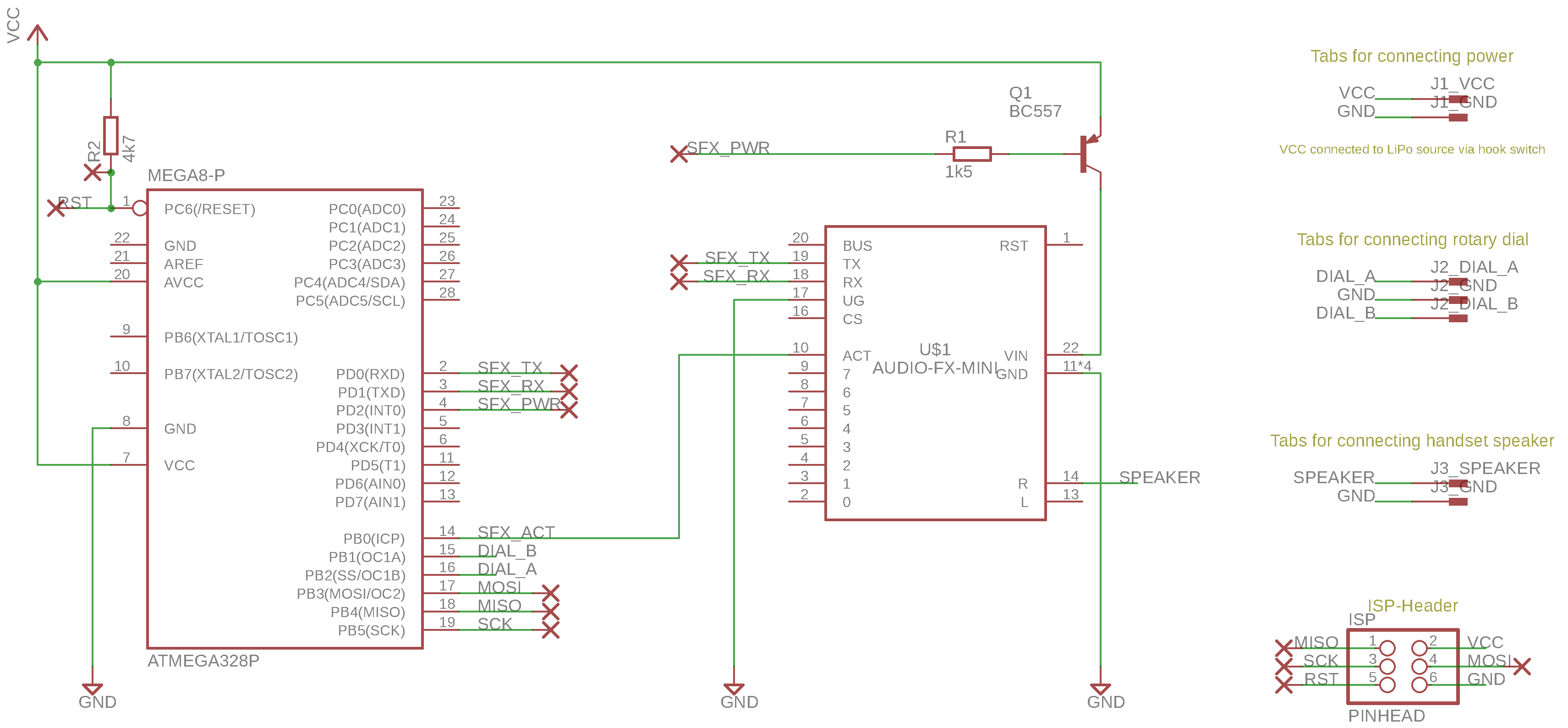
- The microcontroller cuts off the power supply to the sound board (see transistor
Q1in the schematics below). - The microcontroller then enters its sleep mode13.
In this mode the circuit consumes almost now power at all – just leave the handset off the cradle if you like!
Speaking from own experience, waking up sometimes is hard. Fortunately, this is not the case for microcontrollers: An external reset will do. And conveniently this is exactly what happens if you put the handset back on the cradle and then pick it up again: The circuits gets power-cycled, restarting the microcontroller. The user experience is like starting a new phone call.
Building the Final Circuit
With all features successfully prototyped it was now time to build the final circuit. For one-off builds like this (and when space is not an issue) I like to use classic perfboards, because they are cheap and quick to build.
Designing a perfboard-compatible layout in Autodesk Eagle is simple: Just make sure that everything (including the traces!) is aligned to a 2.54mm grid. Most of the time some jumper wires will also be necessary. In earlier projects I often tried to minimise the amount of jumper wires as much as possible, but this makes the traces on the bottom more complicated, leading to longer build times. So this time I used jumper wires more liberally, resulting in an easy to build perfboard.
The layout below shows traces in red and jumper wires as thin air-wires. I also explicitly added wire-pads to the layout to make sure to keep the grid points where the jumper wires would be soldered to the board free from other traces or components.14

.")

Download schematics and board layout (Autodesk Eagle, 40 KB)
As mentioned earlier I used tab terminals identical to those in the phone, so that existing wires could easily be connected to the circuit. Also I used female headers to create a socket for the soundboard, allowing to easily remove or replace it if necessary.
Mounting the Device Inside the Phone
To finish the project I now needed to mount four separate components inside the old phone: The perfboard, the battery, the charging board, and a Micro-USB socket for recharging the battery.
I started with the perfboard. The phone’s enclosure contains some unused sockets which looked like a good fit for fastening the perfboard using small screws. However, because of the board’s size and other components being in the way, in the end I could use only one of these sockets.15 Because a single screw would not hold the board reliably, I then went back to a hack I’d already used in the Lichtspiel: Custom 3D printed spacers with enclosed nuts, glued to the enclosure!
Only one additional spacer was necessary. This kind of mount isn’t rock-solid, but it doesn’t have to withstand strong forces either.


Next, the charging board: I wanted this to be mounted in a way that its status LEDs would be visible from the outside. However, I didn’t want to drill or cut any openings into the phone’s original enclosure.
Fortunately, the enclosure features some ventilation slots. That seemed worth a try: If I could mount the charging board standing upright behind these slots, the LEDs should be visible from the outside.
To mount the board in this position I designed and 3D printed a mounting bracket that could be glued to the enclosure, just like the spacer for the perfboard:


In the end it turned out no to be the most prominent status indicator ever, but it does the trick:
Now I only had to somehow make the charging board’s built-in USB socket reachable from the outside. I opted for a simple extension cable with its own Micro-USB socket at one end. For this socket I could repurpose the opening originally used for the phone cable. Again I decided to design and 3D print a custom adapter which would nicely fit into the opening and carry the USB socket:


Finally, the battery was simply fixed to the bottom of the phone’s enclosure using adhesive tape, right next to the perfboard.
Here’s a picture of the final assembly – no permanent modifications to the original phone, its enclosure, or any of its components had been necessary!

Summary
Surprisingly, this was one of the rare projects where everything went according to plan: Decoding the signals from the rotary dial was trivial, communicating with the sound board worked at the first try, and using a LiPo battery (as well as a charging board) turned out to be more or less a no-brainer.
The phone has now been in use for quite a long time and is still working, even if treated roughly by the toddlers sometimes. There’s only one thing left to do: Sometime in the near future I’ll replace the audio clips with new ones.
Resources
- Schematics and board layout (Autodesk Eagle, 40 KB)
- Source code on GitHub.
-
If you’re from Austria you might remember Zeitansage 1503: “Es wird mit dem Summerton … 18 Uhr, 29 Minuten und 10 Sekunden … piep!” ↩
-
Fortunately there’s quite a lot of empty space inside such old phones. ↩
-
Technically, playing audio is only feasible on Arduinos featuring 32 bit ARM cores instead of the original 8 bit AVR microcontrollers. ↩
-
There are also some dedicated trigger inputs to play predefined audio files, so it can even be used without a microcontroller. ↩
-
Initially I thought about using an ATTiny, but in the end I went with the “classic” ATmega328P because it has more GPIO pins which led to an even simpler circuit. Its larger footprint wasn’t an issue as there was more than enough free space inside the phone. ↩
-
Using the hook-switch that way has the additional advantage of not having to explicitly check its state: Each time the microcontroller boots up it implicitly knows that the handset has just been taken off the cradle. Thus the firmware is programmed to play the dial tone immediately after booting. ↩
-
Technically, this contact is “normally closed”, so the signal is high per default and goes low during each pulse. ↩
-
Of course there’s an exception: Dialling
0generates ten pulses, because it would be inconvenient to deal with zero pulses (how to distinguish between “dialling0” and “not dialling anything at all”?). ↩This also explains why
0is positioned at the very end of the dial, after9: Technically the0is actually a10. -
For programming the microcontroller an USBtinyISP was used. ↩
-
To be exact, LiPo’s provide 3.7V only when fully charged. For an almost empty battery the voltage goes down to 2.8V, which is slightly below the sound board’s required minimum voltage (3V). But that shouldn’t cause any problems – in the worst case the device will stop working a short time before the battery is completely empty. ↩
-
For example, if there was no built-in over discharge protection, to avoid damaging the battery my circuit would have needed to constantly monitor the battery voltage to make sure it didn’t fall below a critical level. ↩
-
AVR microcontrollers feature a range of sleep modes with different characteristics. For this device I used “Power-down” mode (
SLEEP_MODE_PWR_DOWN), which is most effective in terms of power-saving. ↩ -
Later I learned that using vias for this purpose would have been even simpler (more info). ↩
-
At this point I also realised that maybe I should have had made the design of the perfboard a bit less compact: It was really hard to find places where the holes for the screws could be drilled without interfering with existing components or traces. ↩
Hey, this is a really cool project! Thank you so much for documenting all your design choices. I made something very similar based on an ATMega168, and your post was extremely helpful. You can check it out here if you like :)