0026Building a Faux Neon Sign Using LED Strips (Part 2)
2021-09-05
LED strips that look like neon tubes? Terrific! I’ve always wanted to build a neon sign! ´
As a quick recap, at the end of part 1 there were 4 things that bothered me:
- Light leaking from the ends of the LED strips.
- The hollow ends of the strips being noticeably darker than the rest of the strips.
- The letters looking rather thin and fragile.
- And still no idea how to reliably attach that stubborn question-mark-dot.
Let’s try to fix the thin letters first.
Outlines for the Letters!
Doing a bit of research1 made me realise that there are two common ways to avoid the “my letters are looking thin” problem:
- Having the light tubes tracing the font’s outlines.
- Surrounding the tubes with some kind of outline representing a bold font.
Variant 1 was quickly ruled out because of too much work: I would have had to completely rework the existing letters and LED strips.
Variant 2 however looked interesting: Maybe I could cut the outlines from polystyrene on the CNC mill? And if I included a 5mm wide cut-out in the centre, the LED strips would be perfectly aligned.


.")
So far so good! And there even was an additional benefit I hadn’t thought of yet: When the outline layer was glued to the base plate it would help keeping the strips in position. Apart from making the whole setup more sturdy this should also finally solve the problem with the question mark’s dot!
But now it became apparent that the length of the segments did not always match the length of the strokes in the original drawing: The LED strip can only be cut about every 5cm, so some of the strips turned out shorter than originally planned. Up until now I hadn’t cared: Nobody would have noticed the difference, as the sign contained no reference to the original drawing. But with the outlines added this was no longer true: Now the differences in length became obvious.
The only way to fix this issue was to revise the drawing before using it as template for the milling process, adjusting the length of all strokes to be a multiples of 5cm. I decided to use this opportunity to also slightly tweak the form of some curves, making them look nicer when displayed with a thick outline.
Based on the updated drawings I could finally mill the outlines:
Because of the size of the mill’s work area three separate passes were needed: One for “W”, one for “as”, and a final one for “?“.


Fixing the Light Leaking Issue
Now that the biggest problem was out of the way I tackled the two remaining issues: Light leaking from the ends of the strips, and dark sections where the power wires had been attached.
My first idea was to simply cover the ends of the strips with some material. My go-to solution for covering anything is electrical tape, so I tried this first. Using white tape looked decent – but there was still light leaking through the tape.
Next try: Black tape. Now this did block all the light – but the black tape on the white strips looked hideous.
It was not until the following day that the obvious solution occurred to me: Why not simply build a tape sandwich? A layer of black tape covered by a layer of white tape on top should block all the light and still look acceptable:

.")
Another problem solved!
Rethinking the Power Wire Connections
This left me with one final problem: The power wire connections.
The way I had attached the power wires to the strip segments worked perfectly in that the wires were completely invisible. However, as described earlier it required the removal of some LEDs which made these sections look noticeably darker (when the strip was lit).
There had to be a better method of attaching the power wires – time to experiment!
.")


The first try was already an improvement to the original approach, but implementing it was rather time-consuming and involved. However, the underlying principle of using solder pads not at the end somewhere along the strip looked promising, so I tried to refine it:


. The only downside of this approach is that the wires create a small bulge in the strip – but it turned out to be as good as invisible when the strips were mounted to the sign.")
This was the approach I decided to use. Now I had to implement it on all segments used for the letters on the sign. At first I cut off the hollow end from each strip, where the power wires had been attached so far. Of course this made the existing segments shorter – but I had to adjust the lengths of the segments to better fit the new outlines anyway2.
Here’s a sneak peak of how the cabling looks at the backside of the finished sign:

I’m Finally Done – or am I?
Leaking ends covered, unlit (and wobbly) sections removed, thick outline added – by now I had managed to fix all my gripes.
However, the sign still didn’t look right.
It took me some time to actually understand the root cause: Because the outlines (grey) were darker than the base plate (yellow), when the sign was lit in a dim room the outlines merely looked like dark shadows around the bright faux neon letters, making them again look thin and fragile.
Changing the Colour Scheme
Once I had realised the cause of the problem I also knew what I had to do: Change the colour scheme! Having bright outlines on a dark base plate should improve contrast and make the glowing letters look bold under all circumstances.
How about a base plate in dark red? Well, let’s try it out …


That looked promising! Now I needed to find a bright colour for the outlines. For the sake of simplicity – and because I really liked its look – I decided to try using the same colour (a bright warm yellow) I had used to paint the base plate initially.

")

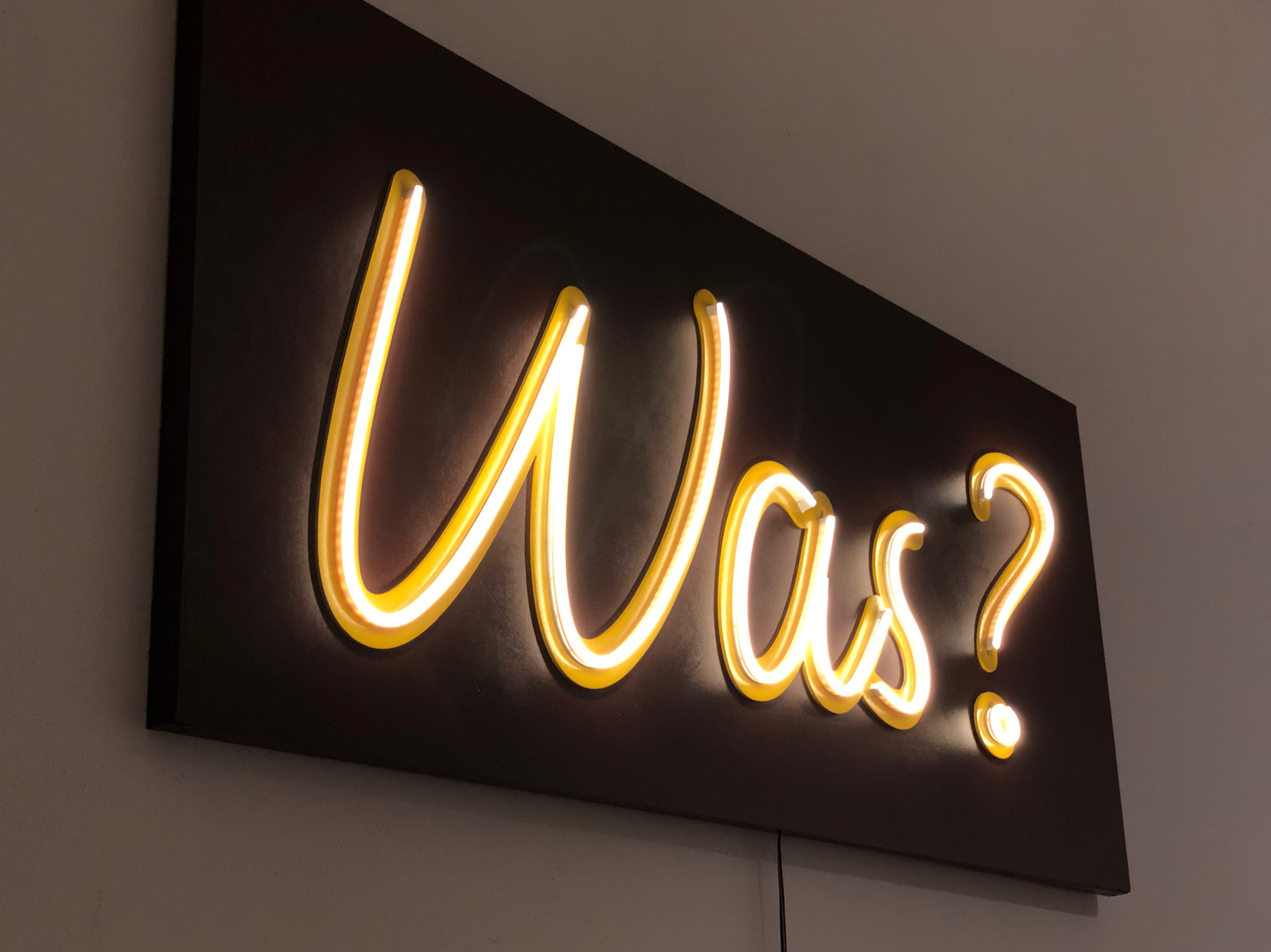
Finally the sign started to look really gorgeous!
And, surprisingly enough, that’s how this story ends. The finished sign was mounted in our office kitchen, where it has been ever since:
 test of the completed sign.")

-
Aka “using google to search for images of neon signs”. ↩
-
For that I had to make most of the segments longer, not shorter, though. However, even if the longest segment was now too short to fit the longest stroke, I could still perfectly use it for the second longest stroke, then use the second longest segment for the third longest stroke and so on. In the end I only had to add one new segment, for the longest stroke. ↩
Leave a comment